Table of Contents
My adventure in Understanding Electric Circuit components and Diode symbols:
A Guide that came from a conversation between me and Chat Gpt. Its for the Confused, the Curious, and well Anyone.
Let’s face it—electric circuits and circuit components and diode symbols sound like stuff you would need to be a wizard or engineer to even think about diagnosing but they also sound a little like places with events focused around 3 rings. Either way it sounds a bit too high tech for us normies but if you are here you are, its either because you’re curious or maybe are trying to fix something and guess what turns out it isn’t as difficult as it sounds. So even if your here because you’ve just realized that slapping the TV remote doesn’t always work. As usual, we’ve got you.
In this guide, we’ll break down diode symbols, LED circuits, and the mysterious world of PCBs (no, not a new sandwich, it means Printed Circuit Board). We’ll make this as simple as explaining how to toast bread—but with fewer crumbs.
STORY TIME
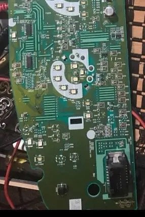
This is a PCB circuit for the dash lights in a motor vehicle. It provides the electric circuit that lights up the speedometer and other indicators like the dreaded check engine light among others.
This vehicles high beam light was not coming on anymore so we set out to see why. Most likely a dead diode but it’s not the only possibility and figuring out which diode is the high beam diode wasn’t even the first problem.… Nope the first thing I had to learn was how identify diodes in general. Yup total noob.
But chat GPT? took one look at the above picture with no prompting at all responded with
“It looks like you’re working on an electronic circuit board. Based on the shape and design, it resembles a vehicle instrument cluster PCB (Printed Circuit Board), commonly found behind a cars dashboard to control and display information such as speed, fuel level, and warning lights.
You also have tools nearby, like a magnifying glass and a multimeter, which are great for inspecting small components and checking electrical continuity.
Are you trying to troubleshoot or repair something specific on this board? Let me know if you need guidance on any part of the process!
What’s a PCB? (And No, It’s Not a Fancy Tech Snack)
I responded with “ yea the high beam”
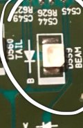
She described to me how to find diodes inspect the board for issues which I could see none, described how to find the high beam diode ( I ended up just lining it up with that dash board indicator cut out the light would come through, low and behold its labeled “beam”
POP QUIZ in the above picture can you find the high beam LED? or identify Any Diode or LED
Time to learn a tech term: PCB. If it isn’t a sandwich then what is it? A Printed Circuit Board
PCB meaning: Printed Circuit Board. It’s the green thing inside your gadgets that looks like a miniature city. The little lines? Those are like roads, carrying electrical “traffic” (a.k.a. current) to different “buildings” (a.k.a. components) like LEDs, resistors, and diodes.
Without a PCB, your phone, computer, or even that funky electric toothbrush would be about as useful as a chocolate teapot. It keeps everything organized, connected, and running smoothly
More of the story
Ok I know the pic was pretty blurry but without lining it up with the dashboard I don’t think I would have found it either.

So I then got to learn about diodes and symbols, and how chat GPT can really aid a google search. Without that boy my search would have ended right after looking at a diode diagram.

THIS ONE
So I took that screen shot and sent it to chat got with the question why is the same diagram labeled as two different things with no discernable difference to this noob SO Chat GPT EXPLAINED
Time to learn about Diods
Meet the diode—the diva of the electric world. It’s a tiny component that only lets current flow in one direction. Imagine a one-way street. You can drive down it, but if you try to reverse, BAM! No dice. That’s exactly how a diode works.
Diode Symbols: It’s Just an Arrow Pointing to a Wall… Sort Of
The diode symbol looks like an arrow pointing to a wall: ▶|. The arrow is the anode (+)—think of it as the entrance door. The wall? That’s the cathode (–), basically a “No Entry” sign if you’re coming from the wrong direction.
Forward Bias vs. Reverse Bias (Or, How to Make a Diode Work or Not Work)
Let’s keep it simple:
- Forward Bias: Current flows like a breeze. Just connect the positive side of your battery to the anode and the negative to the cathode. Boom! Flowing current.
- Reverse Bias: Now flip the battery. The current hits the “No Entry” sign and stops. No current flows. Nada. Zilch.
Think of a diode like a one-way door at a store. Walk in the right way? Easy. Try to exit through the entrance? You’ll either bump into someone or get that “wrong way” glare from the cashier.
CONFESSION TIME
Time for a little admission. .. you see I thought the pictures on the left was one type of diod called a forward diode and the one on the right was a complete other kind called a reverse diode but try as I might I couldn’t understand how these could be discerned from one another when the picture had literally no difference.
I still had no idea what the difference between the two sides of the picture was , until suddenly I realized why. There wasn’t supposed to be a difference . While I thought it was two separate diode types or was only one diode with two ways to measure it to see if it works. forward bias and with pos and neg placed on matching sides and reverse bias with the nodes placed pos to neg and neg to pos ( which should not give a reading because the “walk “ shouldn’t let electricity flow backwards. So now that I knew one way to read the symbol. the arrow points to the direction of the flow and is always the positive side. the line that looks like a wall is always negative side. Forward bias is how it works and reversal bias is how it shouldn’t work, just ways to measure and check a diod is working. finally I also noticed that is what the label under each side is indicating. yu see the diode symbol its showing how it can be being measured forward or backward. forward =flow in a good diod, backward = no flow in any reverse bias diod. its just too bad there is no setting in a multimeter to make sure our brains are working in the right direction I may have realized the problem with it sooner.
Lets learn the rest of the lesson of diod symbols and how to test the components Using a Multimeter:

spoiler it Not as Scary as It Looks
Now, if you’re wondering how to test a diode or any circuit component, you’ll need a trusty multimeter. This is your gadget’s version of a detective—sniffing out faults and misbehaving components.
Here’s how to test a diode (without setting off any sparks, don’t worry):
- Set your multimeter to the diode mode (it looks like the diode symbol: an arrow with a line).
- Touch the red probe to the anode (+) and the black probe to the cathode (–).
- If it’s working, you’ll get a reading (usually around 0.5–0.8 volts). If it’s not working, you’ll see “OL” (which basically means “Open Loop,” aka no connection).
Now, flip the probes to reverse the bias:
- Red probe on the cathode (–)
- Black probe on the anode (+)
You should see “OL” because the current doesn’t flow in reverse. That’s your diode being a good little gatekeeper.
Let’s Talk About LEDs: The Flashy Cousin of Diodes
LED stands for Light Emitting Diode. Yep, it’s a diode that glows when current flows through it. The concept is the same: it lets current flow in one direction. The only difference? This one shows off with light.
When you set up an LED circuit, you’ll notice it won’t light up if connected backward. That’s because it’s reverse biased. Flip it the right way, and voilà—light!
Resistors: The Speed Bumps of the Circuit World
Resistors control the flow of current. Think of them as speed bumps in your electric circuit. You’ve got resistors with values like 10K–100K or 1K–10K, which basically tell you how much they slow down the current.
The bigger the number, the more it resists. A 100–1K resistor lets current flow more freely than a 10K–100K one. Simple, right?
What About Photodiode Arrays?
A photodiode array sounds fancy, but it’s just a bunch of diodes that detect light instead of emitting it like LEDs. They’re like the “eyes” in sensors, detecting changes in light and converting them into electrical signals.
Wrapping It All Up (Without Frying Anything)
So, here’s the cheat sheet:
- PCB meaning: Printed Circuit Board, the “city” where all components live.
- Diode symbols: Arrow and a line. Current flows with the arrow (forward bias), not against it (reverse bias).
- LED circuit: Like a diode, but it lights up when happy.
- Resistors: Circuit speed bumps with values like 10K–100K or 1K–10K.
- Photodiode array: Light sensors, like little eyes for circuits.
Now you (and I )know more about electron devices and circuits and how to read diode symbols than most people who pretend they do. You can impress your friends, fix stuff, or at least not panic when someone says, “Check the circuit board.”
story end… did I find out if the diode was caput? no. it needed to have power to give a proper reading and was in my home not in the vehicle. I actually just kinda piggy backed my roommates project. so I’ll keep you posted on the outcome he comes to. 😉